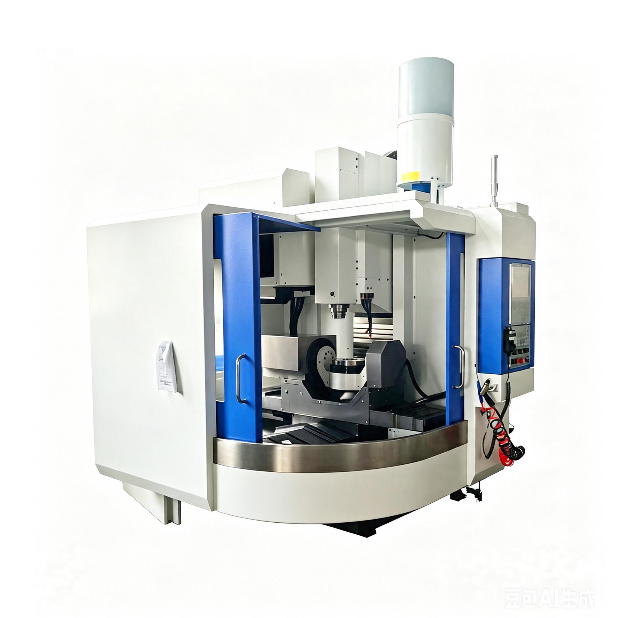
A vertical 5 axis machining center combines a vertical spindle with two rotary motions in the table, head or a mixed arrangement. The best layout depends on part size, setup mass and required tool directions. Buyers should test the loaded workpiece at critical angles because nominal linear travel and table diameter do not describe the true five-axis working envelope.
Compare where the rotary motion occurs
A trunnion-style table can present several faces of a compact part, but the part and fixture move with the rotary axes and must remain within load and center-of-gravity limits. A rotary head can orient the tool around a larger stationary setup, although head size and column clearance affect access. Mixed designs divide those effects. No architecture is universally superior.
Test the loaded envelope
- Place the raw part and complete fixture in the machine model.
- Add realistic holders and gauge lengths.
- Move through every required tool vector and safe retract.
- Check table, spindle, probe, enclosure and chip-clearance collisions.
- Repeat with the heaviest setup and its actual center of gravity.
Choose workholding for access and stability
Five-axis capability can be lost behind tall jaws or broad fixture plates. Clamping should expose required faces while supporting the cutting force and allowing probe access. Define a repeatable zero point and a method to confirm the setup after rotation, interruption or fixture exchange.
Plan chips and fluids at changing orientations
Pockets can trap chips when the part tilts, and coolant may miss the cutting edge at some angles. Review nozzle reach, through-tool delivery, conveyor path and washdown. For dry or near-dry processes, verify extraction and material-specific controls. The chosen arrangement must remain practical for operators to clean and inspect.
Verify the kinematic chain
Rotary-axis center, tool length, thermal condition and control transformations all affect the tool position. Specify calibration routines and a representative multi-axis test, not only individual axis positioning. Keep the kinematic values, postprocessor version and test result under change control.
CNC Tech can review a vertical five-axis application from the part model, fixture, tool list and target operations. That review should confirm the reachable envelope and rotary assumptions before options are priced.
Machine examples and method: compare the AC U400 vertical five-axis machine with the five-axis setup-reduction guide.