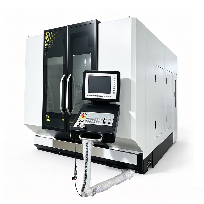
Five-axis machining can reduce setups by bringing several faces of a part within reach of the spindle during one clamping. Fewer reclamps mean fewer opportunities to lose the relationship between holes, bores and machined surfaces. The benefit is application-specific, however: fixture clearance, rotary travel, tool access and inspection strategy decide whether a one-setup process is actually practical.
The error chain behind every reclamp
Removing a workpiece breaks the original datum relationship. The next operation has to find that relationship again through locating surfaces, fixture components, probing or manual alignment. Each step can be controlled, but each also adds time and another source of variation. Keeping features in one clamping shortens that chain.
This is especially useful when a drawing controls the position of features on different faces from a common datum. It can also help on curved surfaces because the machine can keep the cutting tool closer to a favorable angle instead of reaching with an unnecessarily long tool.
Where setup reduction usually pays off
- Multi-face prismatic parts: side holes, angled ports and top features can be connected without moving the part between separate fixtures.
- Impellers and bladed components: coordinated motion provides access between blades where fixed-axis machining cannot.
- Molds and dies: tilting the work can improve tool access to deep or angled surfaces.
- Low-volume precision parts: avoiding several dedicated fixtures may be worth more than chasing the shortest cutting cycle.
Cases where another machine may be the better choice
A simple plate, a high-volume drilling job or a large box section does not become a good 5-axis application merely because one face is angled. A three-axis vertical machine with an indexed fixture may have lower programming, tooling and maintenance costs. Large parts may exceed the usable rotary envelope even when their nominal dimensions appear to fit.
| Question | If the answer is yes | What to verify |
|---|---|---|
| Are critical features located on several faces? | One-clamping machining may protect their relationship. | Datum strategy and probe sequence. |
| Does the tool need compound-angle access? | Simultaneous motion may shorten the tool and improve access. | Collision simulation and post processor. |
| Is the part large or off-center? | The nominal work envelope may be misleading. | Swept envelope, fixture mass and table limits. |
| Is demand stable and very high? | A dedicated multi-setup line may still win on throughput. | Complete cycle and handling study. |
Prove the process before buying around it
Review the part model with the intended fixture, holders and tool lengths present. Confirm which faces are machined in the first clamping, where probing occurs, how the post processor is validated and how the part will be inspected. A representative cut is more informative than an isolated machine specification because it tests the complete chain.
The relevant acceptance method depends on the risk. ISO 10791-7:2020 describes finished test pieces for machining centers, but the buyer and supplier must still agree on the representative part, conditions and limits. For a machine review based on your geometry, share the drawing and production target.