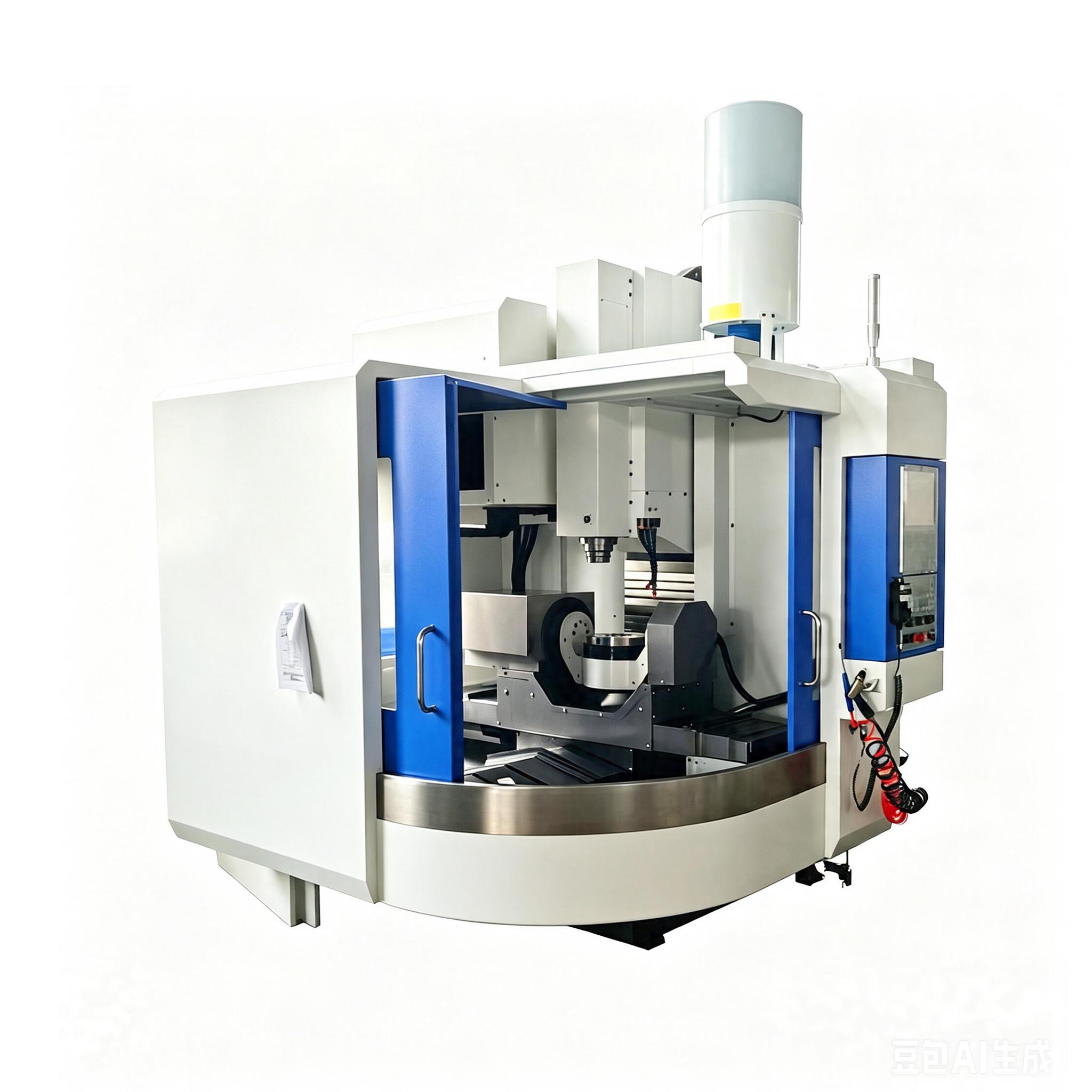
A simultaneous 5 axis machining center moves linear and rotary axes together while cutting. It is justified when continuous tool orientation improves access, controls contact on a complex surface or avoids interruptions that indexed positioning cannot accept. Successful implementation depends on the complete digital and measurement workflow, not merely on enabling five-axis motion.
Identify where simultaneous movement adds value
Mark blades, impellers, ports, sculptured surfaces or swarf-cut walls that need changing orientation through the cut. Other faces and holes may be better handled with stable 3+2 indexing. Separating those operations can simplify programming, reduce rotary motion and make inspection easier without giving up the benefit where it matters.
Keep one consistent kinematic definition
The CAM system, postprocessor, simulation, CNC control and physical machine must agree on axis direction, rotary centers, limits and tool data. Name the owner of post validation and preserve its version with released programs. A control option or head change can require revalidation even when the part program looks unchanged.
- Use actual holders, tools, fixtures and machine solids in collision checks.
- Define safe approach, retract and restart positions.
- Limit rotary motion where cable, fixture or table clearance is tight.
- Set a process for tool-length and probe calibration.
- Verify the finished surface with a method tied to drawing requirements.
Distinguish smooth motion from accurate parts
A visually smooth toolpath can still contain postprocessing, tool-data or kinematic errors. Conversely, aggressive orientation changes may leave marks even when endpoints are correct. Evaluate the actual surface, dimensional relationships and cycle behavior together. Record warm-up and compensation conditions for a reproducible test.
Prepare for interruption
Restarting inside a multi-axis cut requires controlled tool position, orientation and feed entry. Establish procedures for tool replacement, power interruption and program restart before unattended work. Simulation alone does not confirm the physical part, datum and tool are still valid.
CNC Tech can assess a simultaneous five-axis process when provided with the model, CAM platform, tool list, target surface and inspection plan. The review should show where simultaneous motion is necessary and how the complete chain will be proven.
Workflow references: use the five-axis setup guide alongside the U650 machine configuration.