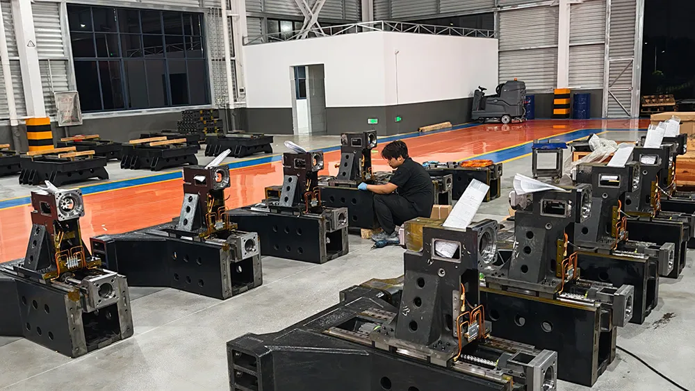
A CNC gantry machining center is most useful when the workpiece needs a wide table, generous clearance and a rigid cutting structure. Selection should begin with the actual part and fixture envelope, not the nominal travel alone. The correct machine must also carry the load safely, reach every feature and fit the customer’s foundation, lifting and service conditions.
Draw the occupied working envelope
Put the largest part, fixture, clamps, probe and longest tool into one drawing. Check the usable distance between columns, under the crossrail and around guarding. A part that fits on the table can still be impossible to machine if clamps enter the toolpath or the spindle cannot reach an edge without overtravel.
Define where cutting force travels
Material, cutter diameter, engagement and tool length establish the duty. Follow the force path through the spindle, ram, crossrail, columns, table and foundation. This review helps separate a machine intended for broad light finishing from one expected to rough steel castings. It also exposes fixture flexibility that a larger machine cannot solve.
| Input | Why it matters | Evidence to request |
|---|---|---|
| Loaded setup mass | Affects table, support and handling | Approved load and distribution conditions |
| Feature locations | Determines usable travel and head access | Envelope review with tool and holder |
| Cutting duty | Sets spindle and structural demand | Representative process or sample cut |
| Acceptance features | Defines accuracy verification | Recorded measurement method and conditions |
Include the building in the specification
Confirm door openings, floor loading, foundation, crane capacity, electrical supply, air, coolant handling and chip disposal before ordering. Leave service space for covers, spindle equipment and electrical cabinets. Transport sections and on-site reassembly can affect commissioning time and the measurements required after installation.
Agree on a reproducible acceptance test
Geometric checks and positioning tests should name the standard, environmental condition, warm-up state and instruments. ISO 230-2 describes methods for determining positioning accuracy and repeatability of numerically controlled axes. Part cutting can supplement those checks, but its material, tools, program and inspection method must be agreed in advance.
For a useful proposal, send CNC Tech the part drawing, setup mass, fixture concept, operation list and site constraints. The reply can then state the machine configuration and acceptance boundary instead of relying on a generic gantry label.
Machine and process references: compare the 8080 gantry machining center with the general machining center selection framework.