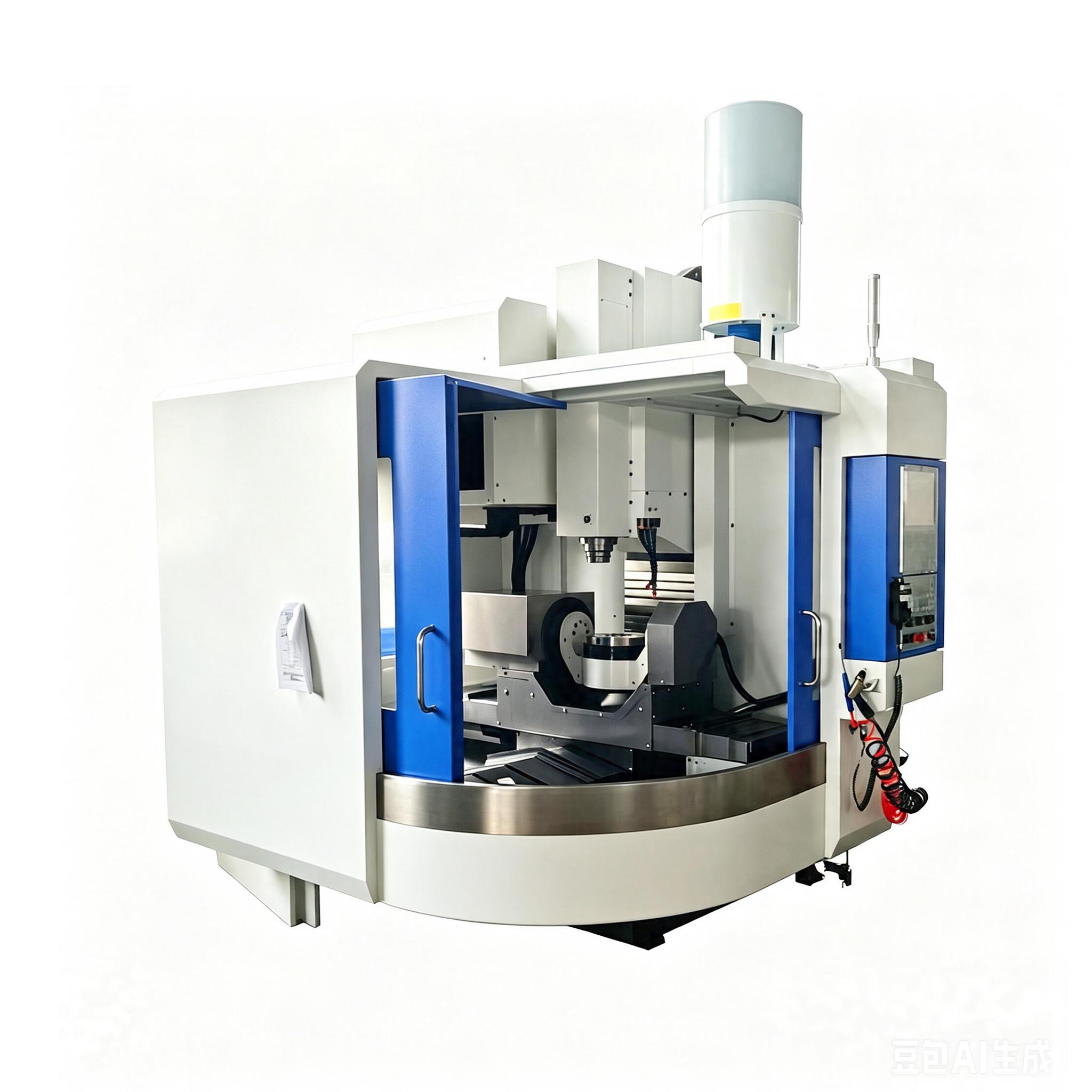
A 5 axis gantry machining center is appropriate when a large workpiece needs features at multiple angles, shorter tool reach or continuous orientation during cutting. Five controlled axes are not, by themselves, proof that the machine can reach a particular feature. The head kinematics, rotary limits, pivot point, tool length and surrounding structure must be checked against the programmed poses.
Begin with tool vectors
Mark the surfaces, holes and undercuts that require orientation. For each one, record the tool direction, holder diameter, gauge length and required approach. This turns “needs five axis” into a set of testable positions. It may show that indexed 3+2 machining covers the job, or that simultaneous motion is essential for a continuous surface.
| Review area | Question | Common oversight |
|---|---|---|
| Head motion | Can the commanded angle be held with the selected tool? | Nominal angle quoted without collision clearance |
| Working volume | Does the full setup fit at every critical pose? | Part fits only when the head is vertical |
| Control | How are tool center point and transformations managed? | Postprocessor responsibility left undefined |
| Verification | How are rotary and linear relationships checked? | Only individual axis travel is inspected |
Assign responsibility for the digital chain
The CAD model, CAM strategy, machine kinematic model, postprocessor, control options and probing routines must describe the same machine. Decide who validates the post, supplies test programs and updates it after a configuration change. Simulation should use the actual heads, fixtures and tool assemblies, not a simplified envelope.
Measure relationships, not just axes
Linear positioning checks do not fully establish five-axis performance. Include rotary-axis geometry, pivot calibration and a representative multi-axis test. ISO 10791-7 covers accuracy of finished test pieces for machining centres and can help frame part-based acceptance, subject to the agreed machine type and test conditions.
Protect access during production
Chip accumulation, probe placement and fixture changes can alter clearance after the first simulation. Define safe retracts, restart behavior and recovery from an interrupted toolpath. Operators also need a clear method for confirming the correct work offset and tool before resuming an angled operation.
Send CNC Tech the solid model, fixture, required tool vectors and planned CAM system. Those complete inputs allow a kinematic feasibility review before spindle power or optional features are discussed.
Five-axis follow-up: read how five-axis machining can reduce setups and review the U650 bridge-type machine.