Gantry vs table CNC usually asks which part of a bridge-type milling machine travels: the bridge over a fixed table, or the table under a fixed bridge. That distinction changes loading and access planning, but it does not make either design universally more accurate. Begin with the part and the material-handling route, then ask suppliers to show the actual motion diagram and prove the required result.
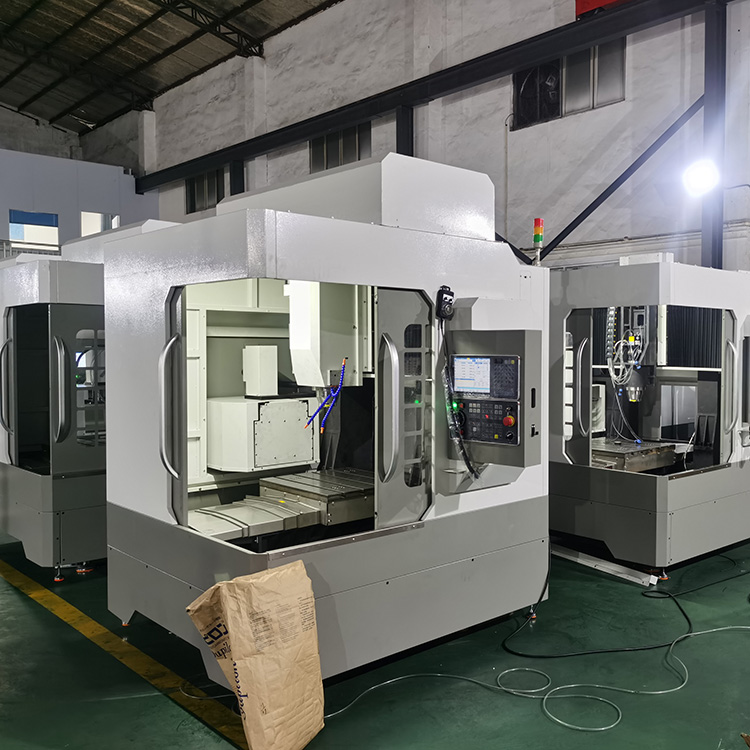
What is actually being compared?
In formal machine-tool terminology, ISO 8636-1:2026 applies to fixed-bridge milling machines with moving tables and fixed double columns. ISO 8636-2:2024 applies to travelling-bridge machines with fixed tables. The documents describe different machine arrangements and accuracy tests. They do not say that one arrangement is automatically better for every part.
The search phrase is sometimes used loosely to mean “gantry machine versus ordinary table mill.” When comparing quotations, remove that ambiguity: request a plan and side view labeling the X, Y and Z motions, the workpiece supports and the fully fixtured envelope. Ask where the operator loads the part and where chips leave the cut.
How the layouts affect a real project
| Planning question | Fixed bridge, moving table | Travelling bridge, fixed table |
|---|---|---|
| What travels in the long direction? | The workpiece and table move under the bridge. | The bridge moves along the workpiece or table. |
| What must the floor plan show? | Table travel and its full swept area, plus load and service access. | Bridge travel, column rails, fixed-part loading and access along the table. |
| What should be checked with the fixture? | Loaded table mass and clearances at both travel ends. | Bridge, ram and tool reach at each critical cutting position. |
| How is accuracy established? | Specified geometry, positioning and representative part tests. | The same classes of evidence, using the applicable machine arrangement. |
These are layout checks, not performance rankings. For example, the moving-table option adds the workpiece and fixture to the moving mass; the travelling-bridge option moves the bridge assembly instead. The effect on cycle time or accuracy depends on the actual design, control, load and process. Do not infer it from the labels alone.
Work backward from the largest part
Send a drawing that includes stock, finished size, fixture, clamps and lifting points. Mark the faces to machine and the datums that must remain consistent. If a large casting must stay in one setup, show how the crane enters and where the operator can reach the fixture. If the part must travel, confirm the full swept envelope and utility clearances rather than reading only the published X travel.
Next, specify the longest tool and spindle orientation. Check reach at the center and extremes of the work zone, including ram extension and bridge clearance. A nominal table size or column span can pass while a clamp or toolholder collides in the real setup. Ask the supplier to annotate the actual drawing instead of confirming fit verbally.
Compare evidence, not adjectives
For each proposal, request the same evidence package: machine and foundation drawing; load distribution and workholding assumptions; geometric and positioning test plan; and a representative cutting trial with agreed inspection limits. ISO 230-1:2012 covers geometric accuracy under no-load or quasi-static conditions. ISO 230-2:2014 covers positioning accuracy and repeatability of numerically controlled axes. A finished-part trial adds the selected tool, material, fixture and cutting strategy to the evaluation.
Record the test environment, instrument, warm-up, program revision and who signs the acceptance report. If a proposal makes a stiffness or accuracy claim without a defined method and location, ask for the missing details. A comparative percentage without a common test setup is not a sound basis for selection.
Use product pages as a starting point
CNC Tech lists the 8050 CNC gantry machining center and 8080 CNC gantry machining center for large-work applications. Their public pages do not establish the exact moving-member arrangement or an acceptance result for a particular order. Request a current configuration drawing and quotation for your part, then compare it against the checklist above.
Plan access and guarding with the cell layout. OSHA’s machine-guarding guidance identifies point-of-operation, rotating-part and flying-chip hazards for milling machinery; the final installation should be reviewed against applicable local requirements.
FAQ
Is a travelling gantry always better for a heavy workpiece?
No. A fixed table can simplify some loading plans, but suitability depends on the actual support, travel, cutting location and acceptance requirements. Compare engineered layouts for the same part.
Is a fixed bridge the same as a standard vertical machining center?
No. A fixed-bridge machine has double columns and a crossrail with a moving table under it. A conventional VMC is a different layout; compare drawings rather than broad labels.
What single document should I request first?
Ask for a dimensioned arrangement drawing with the quoted axes, travel limits, bridge clearance, table, fixture and longest tool shown. It reveals many fit questions before a price comparison.
Sources: ISO 8636-1:2026; ISO 8636-2:2024; ISO 230-1:2012; ISO 230-2:2014; and OSHA machine guarding.