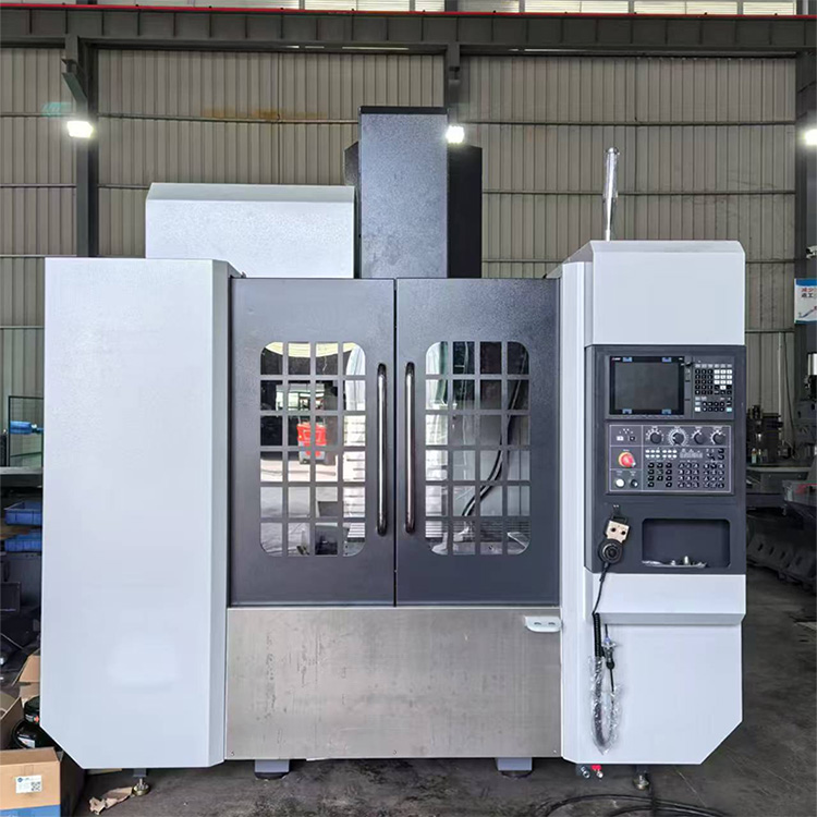
Editorial answer: Centros de maquinado CNC is a broad Spanish buying term that can describe vertical, horizontal, gantry or multi-axis equipment. The useful comparison is the exact architecture and process scope.
Request a Spanish or English proposal that states travels, spindle, table or pallet, control, fixture assumptions and acceptance evidence in one table.
Quick answer
centros de maquinado cnc should be specified from the complete part-and-fixture envelope, the hardest cutting step and the acceptance test. A model name or axis count is not evidence of suitability.
- Send a representative drawing and fixture concept before asking for a final configuration.
- Compare suppliers on the same written scope, including options and exclusions.
- Use a named test piece, measurement method and acceptance limits.
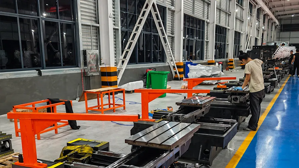
What does “centros de maquinado cnc” mean?
Horizontal machining centers place the spindle axis parallel to the floor. That orientation can help with multi-face work, chip fall and certain palletized processes, but the benefit depends on the fixture, access direction and work envelope. HMC, horizontal milling and machining center terms are not complete specifications by themselves.
The exact phrase may be used differently by suppliers. Treat it as a discovery label, then replace it with a written specification: axes and travels, spindle and tooling, table or pallet, workholding, guarding, coolant, control, installation scope and acceptance method.
Define the process before comparing machines
Map every face that must be machined and the datum strategy used to locate it. Then record tool reach, fixture height, pallet or table size, spindle interface, coolant needs and the longest operation. Ask for a kinematic or layout drawing showing the actual reach with the chosen fixture.
- Part: material, stock, finished envelope, features and critical tolerances.
- Setup: datum scheme, fixture, clamps, pallet or tombstone and operator access.
- Cutting: tools, holders, spindle interface, coolant and chip evacuation.
- Production: batch size, changeover, inspection points and recovery after a stoppage.
- Site: foundation, power, air, coolant handling, lifting route and service clearance.
Comparison checklist
| Question | Evidence to request |
|---|---|
| Can the tool reach the part? | Machine and fixture drawing with the longest tool and clearance shown. |
| Can it hold the required process? | Spindle, axis and workholding guidance tied to the representative material and cut. |
| Can quality be demonstrated? | Test-piece plan, measurement equipment, datum scheme and acceptance limits. |
| Can the cell be operated safely? | Guarding, interlocks, controls and maintenance access described for the installation. |
| Can the quotation be compared? | Line-by-line scope separating standard equipment, options, buyer supply and exclusions. |
Evidence and acceptance
Ask the supplier to identify the measurement reference, environmental conditions, warm-up procedure and instrument used for each critical result. ISO 230-1 describes test methods for machine-tool geometric accuracy under no-load or quasi-static conditions; ISO 230-12 covers accuracy of finished test pieces. Those standards do not replace a project-specific acceptance plan, so name the part, features, tolerances and responsibility for measurement.
Safety review belongs in the same project record. OSHA describes the point of operation, power-transmission devices and operating controls as machine-guarding areas, and its general requirements address hazards such as rotating parts, flying chips and sparks. Confirm the guarding and interlock arrangement with the responsible installer and your local requirements.
Relevant CNC Tech product references
For a starting point, compare the current product pages for U650 bridge-type 5-axis machining center and AC U400 vertical 5-axis machining center. Treat these pages as product references, then request the latest drawing, option list and quotation for your part. If the application is unusual, send the drawing and process details to CNC Tech for a configuration review.
Frequently asked questions
Is the highest axis count always the best choice?
No. The useful choice is the simplest configuration that reaches the features, holds the process and meets the inspection plan. Extra axes can add capability and programming requirements; verify the process before paying for them.
What should be in a machine quotation?
It should identify the model, travels, spindle and tooling, workholding assumptions, options, installation scope, training, documentation, exclusions, delivery terms and acceptance test. Ask for a revision-controlled specification.
How do I avoid comparing unlike machines?
Use one representative part and one written scope. Compare the same material, fixture, tools, coolant, program assumptions and measurement method. A bare catalogue line is not an equivalent offer.
Sources and further reading: ISO 230-1:2012 (geometric accuracy test scope), ISO 230-12 (finished test pieces), and OSHA machine guarding guidance. Review applicable local regulations and the final machine manual before installation.