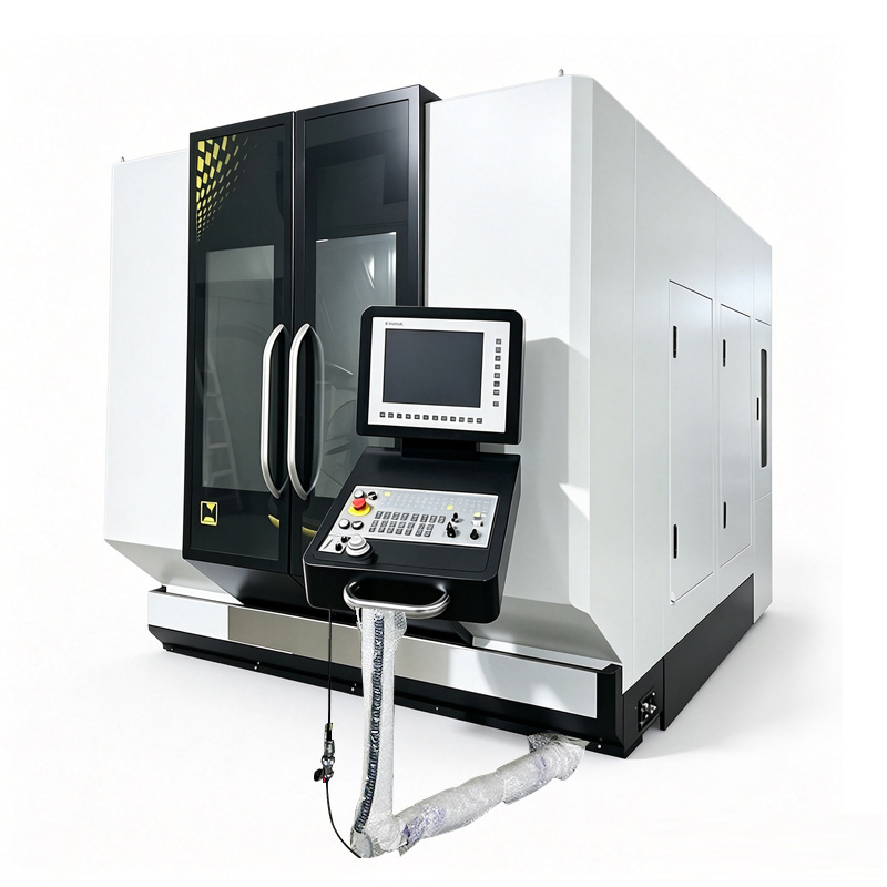
CNC Tech has introduced a new-generation 5-axis machining center for parts that require access to several faces or continuously changing tool angles. The release adds another option for mold, impeller and precision-component work, but the machine still has to be configured around the actual part. Travel, rotary-axis capacity, spindle choice, control functions and inspection requirements should be confirmed in the final technical proposal.
Why a 5-axis layout changes the process
On a three-axis machine, an angled hole or a feature on the back of a part often means another fixture and another alignment. A 5-axis machine can orient the workpiece or the cutting tool so that more of those features are reached in one clamping. The useful result is not simply “five axes”; it is the ability to keep related features in one coordinate system and reduce hand-offs between operations.
That advantage is strongest on parts with several machined faces, compound angles or surfaces that are difficult to reach with a short, rigid tool. A flat plate with simple top-side features may still be produced more economically on a three-axis vertical machining center.
Details to settle before selecting the machine
| Review item | Why it affects the result | Evidence to request |
|---|---|---|
| Rotary-axis layout | It determines part access, fixture clearance and the usable work envelope. | A clamping sketch or simulation using the buyer’s model. |
| Part and fixture mass | The rotary table must carry the complete assembly, not only the finished part. | Approved load calculation and fixture concept. |
| Spindle and tool interface | Material, tool diameter and duty cycle change the torque and speed requirement. | A process sheet tied to representative operations. |
| Control and CAM functions | Post-processing, tool-vector control and collision checks affect commissioning time. | Control option list and a confirmed post-processor plan. |
| Acceptance method | Axis positioning tests and finished-part tests answer different questions. | Written factory and site acceptance procedures. |
What the announcement does not establish
A launch notice cannot prove cycle time, surface finish or finished-part accuracy for every application. Those results depend on the selected machine configuration, toolpath, cutting tool, workholding, material, temperature and measurement method. Buyers should treat catalogue data as a shortlisting aid and put the values that matter into the quotation and acceptance plan.
For test-method context, ISO 230-2 addresses positioning accuracy and repeatability of numerically controlled axes, while ISO 10791-7 covers the accuracy of finished test pieces for machining centers. The standards describe methods; the purchase documents still need to state the agreed limits and test conditions.
Discussing a real application
A useful application review starts with a 3D model, material, blank size and mass, critical tolerances, surface requirements, annual quantity and the operations planned before and after machining. CNC Tech can then review access, fixturing and machine configuration against the actual part instead of relying on a broad “5-axis” label. Send the application details when those inputs are ready.